Smart Room Comfort Guardian
Overview
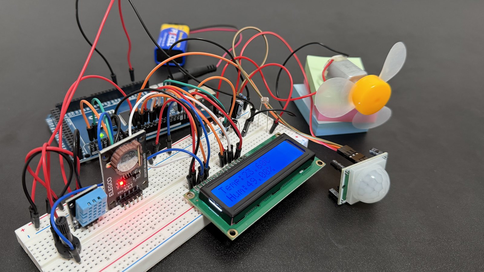
I built a room monitor on an Arduino Mega 2560 that reads temperature, humidity, light and motion. It decides whether the room is comfortable, and turns on a fan by itself when someone is in the room and it's too warm.
Outcome: The Comfort Guardian senses, decides and acts all on one board, and its daily temperature record is saved, even when unplugged.
- Year
- 2026
- Tools
- Arduino Mega 2560, C++, Arduino IDE, Claude
An Arduino is a small, single-purpose computer that reads sensors and controls things like lights and motors. This project combines three sensors to control when a fan runs. It only decides to kick in when the motion sensor says the room is occupied and the temperature sensor says it's above 26 °C.
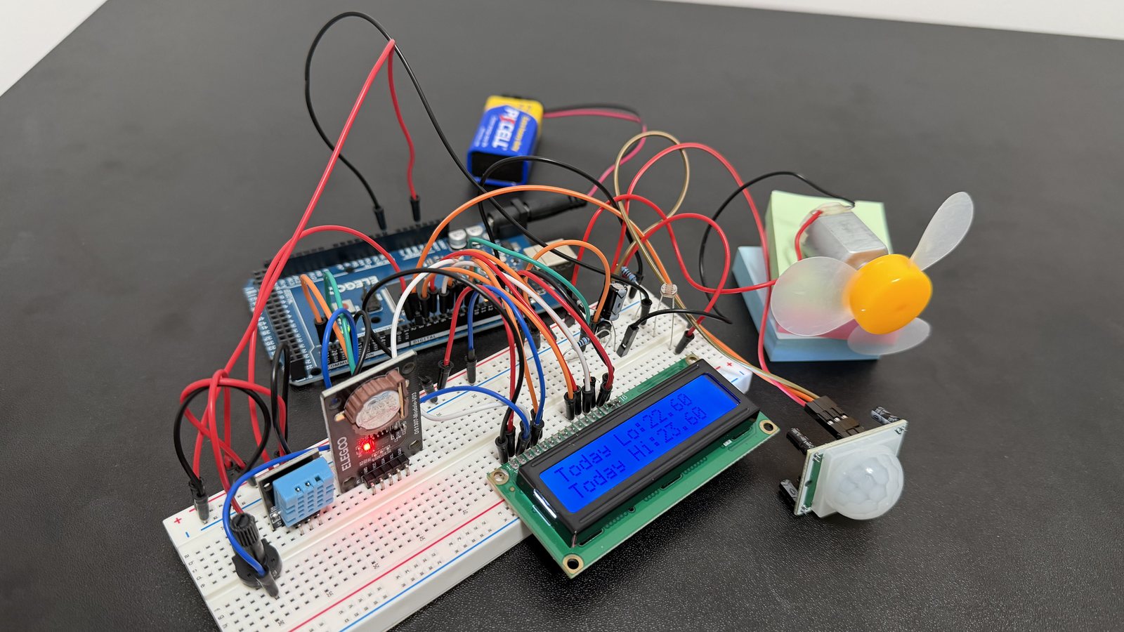
An LCD screen cycles through five status screens, so you can read the system without a laptop attached. It also has a real-time clock, a temperature trend (rising, falling or stable), and a daily high and low record that survives even when unplugged. I built it step by step, testing each one before starting the next.
Skills
- Arduino
- Circuit design and breadboarding
- Analog and digital input and output
- EEPROM data storage
- Transistor switching circuits
- Sensor decision logic
- Hardware debugging
- AI-assisted development
01 · Choosing the Hardware
For this project, I used a temperature and humidity sensor, a motion sensor, a light sensor, a real-time clock, an LCD screen and a small fan motor. All came with an Arduino starter kit I had lying around.
Why the Mega
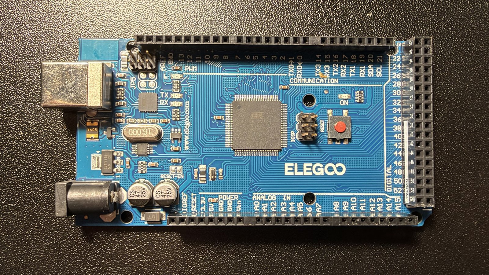
I had both an Arduino Uno and a Mega 2560. I chose the Mega because it has more pins, the connection points everything plugs into. Three sensors, a clock, a screen that needs six data pins, and the fan all run at once, and the Mega fits them all.
Memory on the chip
The Mega also has built-in EEPROM, memory on the chip itself that keeps its contents with the power off. It doesn't hold much, but it's enough for a daily temperature record, so no extra storage was needed.
02 · Reading the Room
I added one sensor at a time, and each one got its own small test program before joining the main program.
Temperature and humidity
The first sensor was a DHT11 on pin 2. Its first reading was 29.5 °C, which was way off (I was in the comfort of my basement). I realized that the sensor was warming up and picking up heat from the board beside it, not broken, so I moved it away and the readings started to look more accurate.
A display, and a power problem
Next came the LCD, a screen that shows two lines of 16 characters. A small adjustable knob (a potentiometer) sets its contrast.
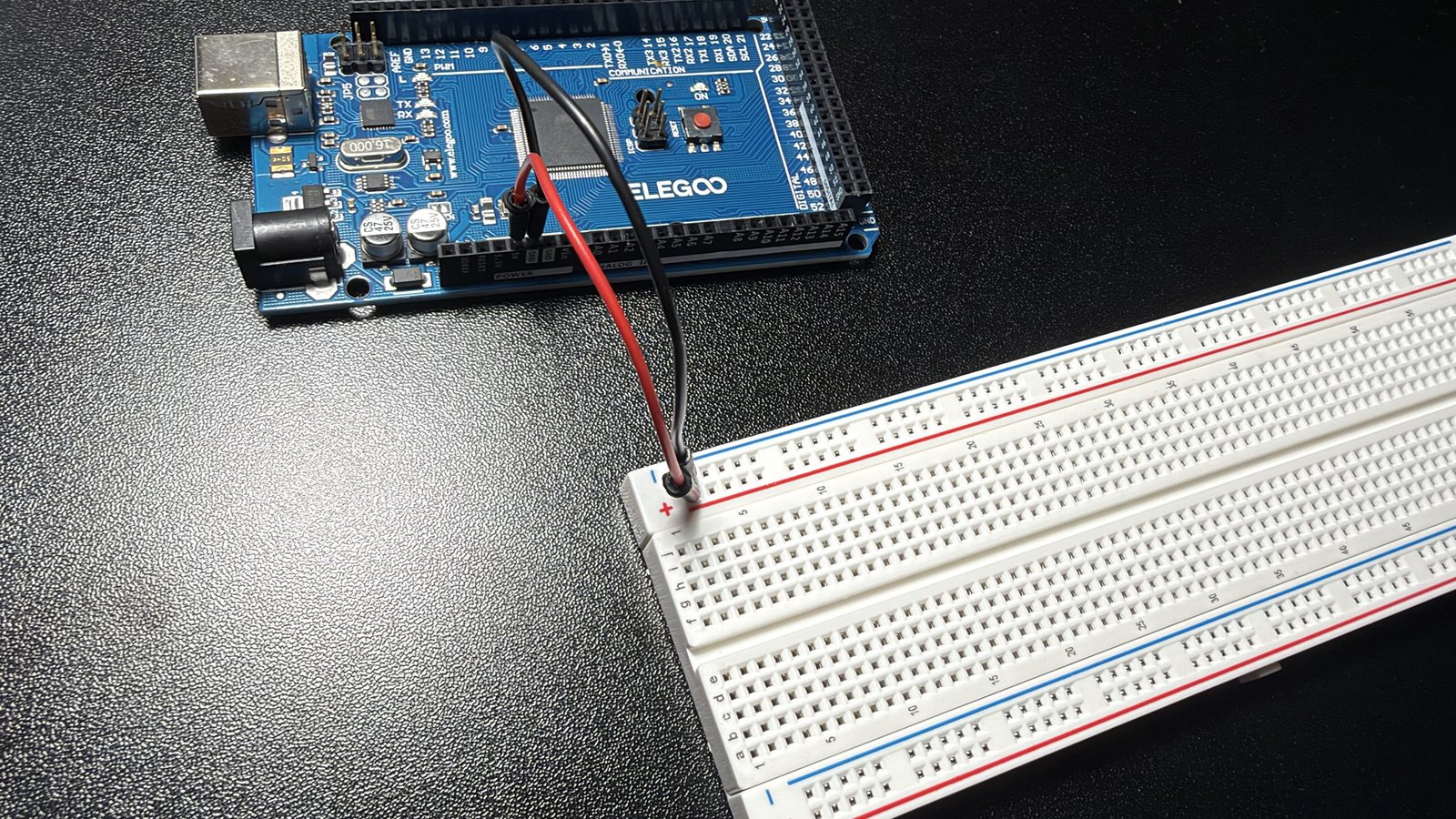
The LCD needs power on several of its pins, but the Mega has only one 5 V pin. I ran that pin to the breadboard's power rail, a long strip that shares power with everything plugged into it, and powered every part from the rail. Every sensor after that followed the same pattern.
Light
A photoresistor is a light sensor that measures how bright the room is. It lets the Comfort Guardian tell whether the room is lit or dark, which shows up on the screen as "Lit" or "Dark".
Motion
The PIR motion sensor detects changes in infrared heat, like a person moving. It needs about 30 seconds after power-up to learn the room, so the program waits before trusting it. At first it missed some hand movements, but turning up its sensitivity dial fixed most of the misses.
03 · Making Decisions
With all three sensors working, the next step was turning numbers into decisions.
Translating readings
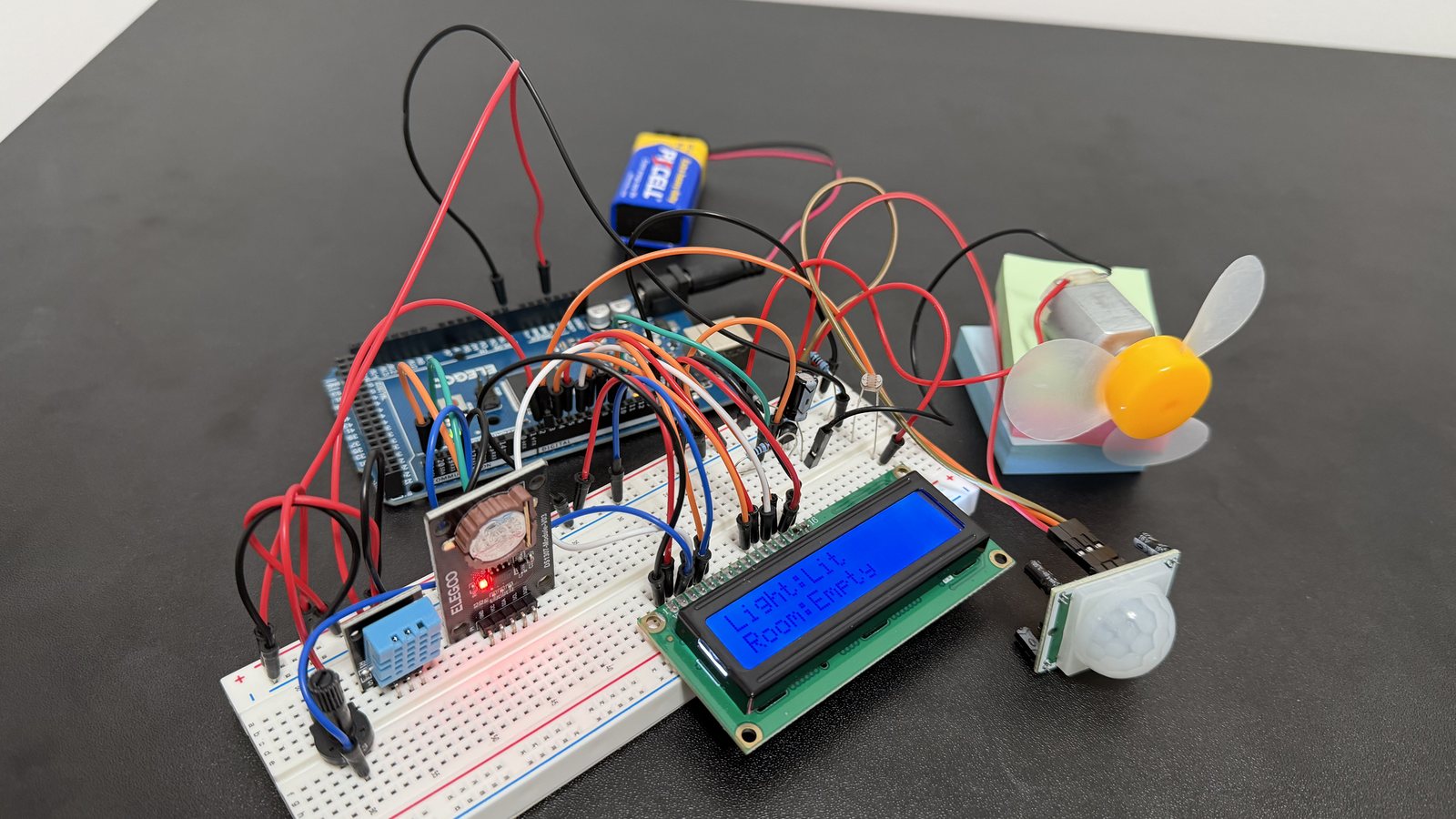
Above 26 °C is "Too warm", below 18 °C is "Too cold", and anything between is "OK". The light reading becomes "Lit" or "Dark", and the motion sensor becomes "Occupied" or "Empty".
All this data on a 16×2 display?
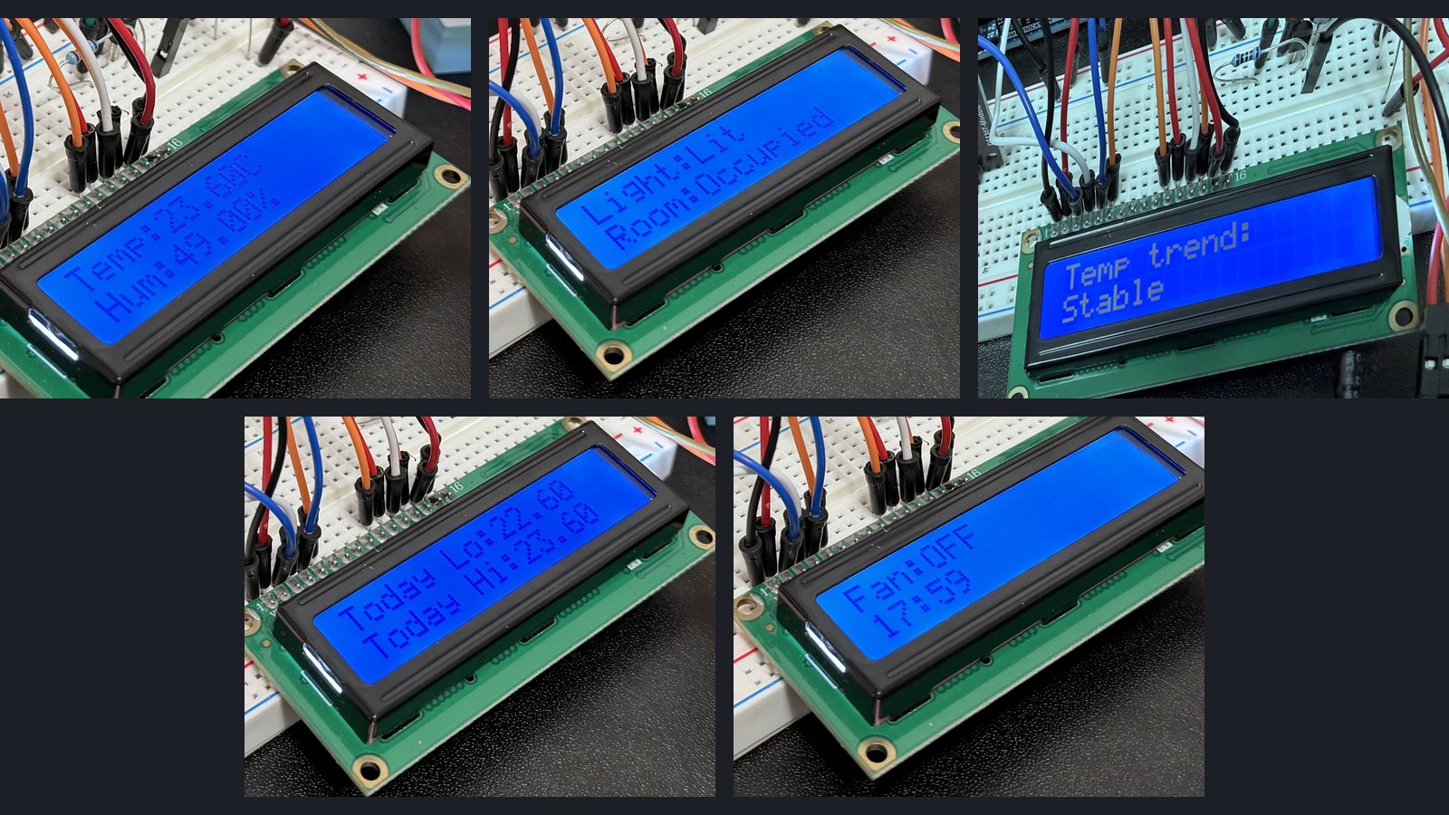
The LCD only fits 32 characters, far too few to show everything at once. So the program cycles through five screens, two seconds each:
- Temperature and humidity
- Light level and occupancy
- Temperature trend (rising, falling or stable)
- Today's low and high
- Fan status and the current time
The fan rule
The fan runs only when the room is occupied and above 26 °C.
In code, that's a single line: shouldBeOn = (motion == HIGH && temp > 26).
Stopping the flicker
A temperature hovering right at 26 °C, or a motion sensor blinking on and off, would switch the fan on and off every few seconds. I added a 10-second cooldown, so the fan can only change state once every 10 seconds.
04 · Giving It Memory
Up to this point, unplugging the system erased everything. This step makes sure the records survive when the system is turned off.
A clock that keeps running
The DS1307 real-time clock is a clock chip with its own coin-cell battery, so it keeps time even when the Arduino is off. I set it once by copying my computer's time, then changed the code so it only reads the time. Otherwise, every upload would reset the clock.
Rising, falling or stable
The program remembers the last 10 temperature readings, with each new reading replacing the oldest. A trend is calculated by comparing the newest and oldest reading. If the newest reading is more than 0.5 °C above the oldest, it's Rising. If more than 0.5 °C below, it's Falling. Anything else, Stable.
Surviving a power cut
The daily record holds the date, plus the lowest and highest temperature and humidity seen that day. It's saved to EEPROM and loaded back at startup, and when the date changes, the record starts over for the new day.
To make sure it actually worked, I unplugged the whole thing and plugged it back in, and the day's high and low were still there, right where I left them.
05 · The (doomed) Relay
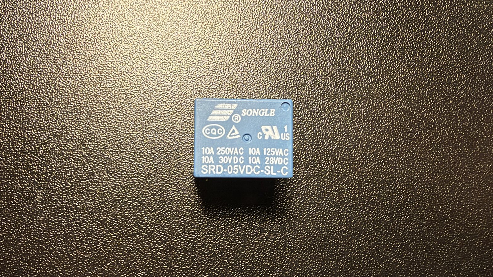
A project like this always has problems, right? The last piece was switching on the kit's small fan motor. An Arduino pin can only supply a tiny amount of current, nowhere near enough to run a motor, so it needs something in between. I planned around using a relay module (a relay on a small board with labeled pins and its own driver circuit).
The first test half-worked. The screen showed "Fan: ON" and the relay clicked, but the fan didn't spin. To narrow it down, I disconnected the motor and touched its wires straight to the power rails, and it spun. So the motor, power, and logic were fine, and the problem was somewhere in the relay (turns out, the "relay" I had was just the bare part, without the board and circuit a module comes with!).
Debugging with Claude, I discovered that the relay needs about 70 mA to switch, but a Mega pin is only rated for 20 mA. Driven straight from the pin, it got barely enough current to click at first, then not enough at all.
Building a transistor switch instead
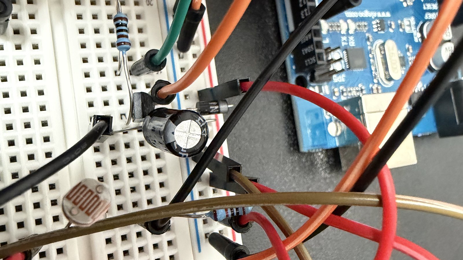
Continuing to debug, I discovered that the motor didn't need to use a relay at all. A PN2222 transistor, already in the kit, can switch it directly. A transistor is an electronic switch with no moving parts: a tiny current from the Mega controls the much larger current running the motor.
06 · The Screen That Wouldn't Stay Clean
I guess I can't catch a break. The fan spun on the first try with the transistor. At the same moment, the screen filled with random characters, and it stayed that way after the fan stopped. Only unplugging the Mega fixed it.
The screen is set up once, when the Mega starts. If a burst of electrical noise scrambles a command partway through, the screen stays scrambled until it's set up again.
My first guess was a voltage issue, and I assumed the motor was drawing a burst of power as it starts. I tried two different solutions:
- A capacitor across the motor, a tiny bit of stored charge to cover that burst. No change.
- More power. I powered the Mega from the kit's 9 V wall adapter instead of USB. Still no change.
With more power available and the glitch unchanged, I didn't think it was a voltage issue. My next guess was electrical noise from the motor interfering with the screen.
A fix in software
I resorted to fixing the screen in software. Every time the fan turns on or off, the program waits 50 milliseconds, then sets the screen up again.
The glitch still happens, but now it clears in a fraction of a second instead of lasting until the next unplug. It isn't the cleanest fix, but it sufficed and allowed everything to function correctly.
07 · AI?!
I did get some help from Claude, as it helped with the code while I worked on the hardware. Claude also assisted with debugging individual issues with the sensors, and figuring out the problem with the relay.
What I learned
Check the hardware before designing around it. My biggest detour, the relay, came from assuming what a part could do instead of checking it.
Not every fix has to be in hardware. When the screen glitch couldn't be solved via hardware, a few lines of code got everything working again.
What comes next
If I were to continue this someday, I would want to turn it into something more than just "fan turn on when room hot", and make it something more useful, maybe something that sits at your desk and turns on the fan and a desk light right when you're about to study. I'd also want to turn this into a cleaner-looking build with a proper 3D-printed enclosure, but that'll come when I actually decide to get a 3D printer.